|
|
|
Keynote general
|
|
Braided headdbands
|
|
|
Loop braiding
|
|
|
Kumihimo jewelry
|
|
Kumihimo for textile composites
|
|
|
|
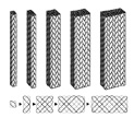 |
| Fig. 1 A family of the square-braid. |
| Ā |
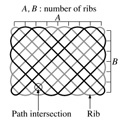 |
| Fig. 2 Optimum number of bundle Nb of square braids |
| Ā |
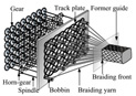 |
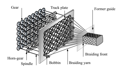
| Fig. 3 Proposed rotary braiding machine system. |
| Ā |
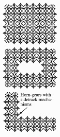 |
| Fig. 4 The arrangements of horn-gears with sidetrack mechanisms
for the rotary braiding machine. |
| Ā |
|
|
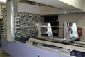
| Fig. 5 3-D rotary braiding machine |
| Ā |
|
|
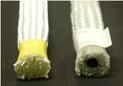
| Fig. 6 A 6x8 square and a 6x8 hollow square braid. |
|
|
Kumihimo for Textile Composites
|
Makiko Tada
|
|
Introduction
This study deals with braiding structure and methods of braids. Braids can provide
continuous bundle arrangement in the axial direction and can bear the axial loads
with all the bundles. Braids can be made in thick, hollow, solid or irregular cross-sections
and can be easily manufactured in a 3-D form in an automated manner. Thus braids
has been expected to be an excellent reinforcement for composite materials.
A wide variety of braided structure can be found in the historical braids of Japan
where the exclusive braiding culture was developed (1). On the contrary, braided
structures available for the present composite materials have been determined simply
by the availability of the braiding machine and not by the mechanical functionality.
Thus, an investigation into the historical braided structures may lead to an introduction
of more rational braided structure for the reinforcement of composite materials with
higher modulus, strength and functionality than those found in the present machine
braids, thereby this study begins with an investigation of the historical braided
structures which will then be translated into the rotary braiding machine processes.
Number of Bundles of Coupled Square Braids
A series of square braids which may have been braided by the loop-manipulation techniques
in the Hian (784-1185) and the Kamakura (1185-1333) periods were focused and their
braided structures and braiding procedures were analyzed to translate their structures
into machine braiding procedures (2). The targeted braids were the solid square type
with 2x2, 2x4, 4x4, 4x6 and 4x8 ribs as shown in Fig. 1 and their bundle path diagrams
and the number of paths were studied.
A formula determining the optimum number of bundles for the square braids can be
derived as a function of the number of ribs which is the number of bundles present
at the perimeter of a braid, and the number of path intersections which is the number
of apparent cross point of bundle paths available in a bundle path diagram.
The most stable braided structure can be obtained when all the bundles intersect
always by turns; each bundles have only one to one intersections like plain weaving.
On the contrary, bundles may form a ędefectė in a braided structure when they pass
the path intersections without crossing. In a braid with the most stable structure,
there is only one bundle present at a path intersection as well as at a perimeter.
Thus the optimum number of bundle Nb can be given as the sum of the number of path
intersections, Npi, and the number of bundles turning at the perimeter, Npr, shown
in a bundle path diagram.
The number of bundles turning at the perimeter corresponds to the number of ribs
that may be formed at the perimeter of a completed braid. Assuming that a square
braid comprises a side with a number of rib, A, and the other side with a number
of rib, B, as shown in Fig. 2, the number of path intersections, Npi, and the number
of bundles at the perimeter rib, Npr, can be given as functions of A and B.
Npi = B(A -1) + A(B -1),
Npr = 2(A + B) - 4,
Nb = 2AB +A + B - 4. |
(2)
(3)
(4)
|
The optimum number of bundles must be known when the braiding process is mechanized.
If the number of bundles is greater than the optimum number, more than one bundle
may intersect with a bundle of another path, resulting in the time-lag of the spindle
exchange and the number of horn-docks. Because the number of horn-docks may be greater
than that of the ęwaitingė bundles, the number of horn-docks in a horn-gear must
be varied according to the total number of bundles, while the number of horn-docks
in a horn-gear becomes constant when only each one bundle exists at a path intersection
and at a perimeter rib. Determination of the optimum number of bundles is therefore
important for the rotary braiding machine capable of manufacturing various type of
braids with an unitized spindle exchange mechanism. A general method to draw the
bundle path diagram of square braids, particularly untwisted square braids, was also
established.
Application to Braids with Hollows and Other Irregular Cross-sections
The method to determine the optimum number of bundles can be applicable to square
braids with hollows or other irregular cross sections. A L-shaped square braid, for
example can be approached as follows. The L cross section can be considered as the
result of subtraction of a small square from a large original square with the number
of ribs of A and B. Because we consider untwisted braids only, A and B must be an
even number. Denoting the number of ribs of the small square a and b, the number
of path intersections for the small square, Npis, can be given by
| Npis = 2(a - 1)(b - 1) + 1. |
(5)
|
Because the optimum number of bundles for the large original square, Nbl, can be
given by
| Nbl = 2AB + A + B - 4, |
(6)
|
the optimum number of bundles for the rest L square braid, Nb, yields
| Nb = Nbl - Npis = 2AB + A + B - 2(a
- 1)(b - 1) - 5. |
(7)
|
Machine Braiding of 3D Braids
Correlating the bundle path diagram and the number of bundles, a general method to
translate a structure into rotary braiding machine procedures was developed. For
braiding machine applications, design and arrangement of horn-gears and the number
of necessary horn-docks were studied and consequently, the possibility to develop
a rotary braiding machine capable of braiding a wide variety of braids was found.
As the minimum unit of the square braid, a 2x2 square braid can be made with a 2x2
number of horn-gears with 4 horn-docks. When the number of ribs increases, small
horn-gears with 4 horn-docks are arranged at each corner, large horn-gears with the
same number as that of the rib with 5 horn-docks are arranged at the perimeter and
the rest of the space are filled with large horn-gears with each 4 horn-docks.
Instead of the horn-gear with each 5 horn-docks, a simpler mechanism consisting of
a 4 horn-docks with a sidetrack was designed and applied to a prototype 3D braiding
machine. The sidetrack switches a spindle one step back when the spindle travels
over a horn-dock at a corner: the spindle is taken out, kept waiting for a moment
and brought back to the next dock. System of a rotary braiding machine capable of
braiding the 3D braids is shown in Fig. 3. The arrangement of horn-gears with a sidetrack
and a 4 horn-docks for a solid-square type, a solid-hollow type and a L-shaped square
braid is shown in Fig. 4.
As a consequence, the 3D rotary braiding machine was successfully manufactured as
shown in Fig. 5. It is important to note that, when the 4 horn-docks with a sidetrack
is used, all the horn-gears can rotate in a constant speed without collision of spindles,
which can be accomplished only by design without a help of change gears or computer
control. The maximum dimension of the solid square braid that can be manufactured
with the prototype braiding machine was designed to be 6 x 8 allowing straight center
bundles where necessary. The 3D rotary braiding machine is working in a truly accountable
manner without collision of spindles. Square braids with a hollow and L-shaped square
braids were also manufactured with the same prototype machine by exchanging a track
plate and horn-gears. Examples of a solid square braid and a square braid with a
hollow are shown in Fig. 6 as a proof of the innovative design method and a correct
horn-gear arrangement. It is noticeable that the 3D braiding machine can manufacture
various square braids of arbitrary cross sections, within the limitation of 6 x 8
number of ribs, by exchanging track plates and horn-gears. Thus a very flexible braiding
machine capable of manufacturing square braids of various cross sections to meet
a variety of functional requirements was successfully developed.
Conclusions
The machine braiding methodology was extended over thick square braids, hollows and
many other irregular cross sections such as L, C, T and I-shape, and the bundle path
design method necessary for the machine braiding was developed. A formula determining
the optimum number of bundles for the thick square braids, hollows and other irregular
cross sections was derived and the design method to arrange horn-gears and the system
of horn-docks were presented. A rotary 3D braiding machine was built and is working
satisfactorily.
This study is characterized throughout by the translation of the traditional knowledge
into the advanced composite technology with a special emphasis of developing mechanically
optimized braiding structures, which may be of academic, industrial and cultural
significance.
References
1. Tada, M., Proceeding of 4th Int. Symp. Textile Composites, Kyoto, O-41-1(1998)
2. Tada, M., Uozumi, T., Nakai, A. and Hamada, H., Composite Part A, Elsevier, 32,
1485- 1489 (2001) |
|